

Hacking Sonoff T4EU1C with ESPHOME
What’s this? A no-neutral WiFi-controlled smart switch made by Sonoff?
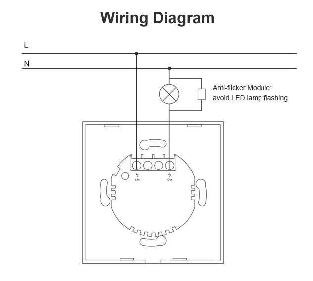
Yep, that’s right. Just like the previous TX models (Touch, T1, new-T1, T2, and T3), the T4 can be wirelessly controlled with the eWeLink app, or the touch sensor, and has a small LED to help you locate the switch in the dark. And best of all, there is no neutral connection required - only live in, and out (to the light bulb). Want to know more about how it works? I suggest watching this YouTube video by SuperHouseTV.
Before you go out and buy one for yourself, it’s important to note the few cons which exist with the new T4’s.
- Firstly, they will (most likely) not work with any device which isn’t as light bulb. You cannot use them as a general-purpose smart switch.
- Also, LEDs and CFLs are supported, but require you to connect the included “anti flicker module” in parallel to the bulb(s).
- 443 MHz is not supported by the T4 model, incase you were one of the three people in the world who actually used this feature.
Like all of Sonoff’s products, the T4 is really easy to flash with your favourite custom firmware. I decided to go with ESPHome, because of the easy integration with Home Assistant and super easy yaml configuration, but tasmota and espurna will also work.
How should I flash?
For the first flash, you will most likely need to connect via UART. See below as to why SonOTA currently doesn’t work.
SonOTA
Sadly, the devices appear to all ship with firmware version 3, and are therefore not compatible with SonOTA. Even if SonOTA does end up adding support for v3, I would not recommend using this method. The device is designed to be easily taken apart, and it’s super easy to connect up to it via serial.
Serial
Raspberry Pi
If you happen to have a Raspberry Pi (or similar SBC with 3v3 UART interface), you could use it without the need for an adaptor. This is the method I ended up choosing, as I did not happen to have a TTL-USB adaptor laying around, although I cannot recommend it for beginners. For further information, I recommend following these two guides:
PORT: Will most likely be /dev/ttyS0 on a RPI 3/4 or /dev/ttyAMA0 on a Pi 1/2/zero
TTL-USB Adaptor
The CH340G appears to be the most common USB-SERIAL adaptor, although others (like FTDI FT232 or CP2102 will also work). They are extremely cheap, especially from eBay or AliExpress, and are extremely useful. It’s never too late to pick one (or 5) up. Be aware though, any ESP866-based device might get fried by 5v. Always remember to set your adaptor to 3v3.
PORT: Depends on your OS. On Linux, it is likely /dev/ttyUSB0. On Windows, COM1 and on MacOS, /dev/tty.usbserial.
An alternative if you don’t have either of the above - NodeMCU or other development board!
Many ESP8266 / ESP32 development boards come with an onboard USB port, TTL-USB adaptor and 3v3 regulator. In this example, I use a NodeMCU, but you do not need to do the same. Just make sure your device is 3v3 not 5v (eg. many Arduino’s), as this may fry your Sonoff T4.
| NodeMCU | Sonoff |
|---|---|
| 3v3 | 3v3 |
| GND | GND |
| TX | TX |
| RX | RX |
Note:
- The TX and RX pins are “backwards”. This is correct.
- GND must also be connected to the NodeMCU’s ENable pin. This disables the NodeMCU.
You can then plugin in your PC / Laptop to the development board via USB.
Compiling your binary
This step will depend on which firmware you decide to use. ESPHome has a convenient setup wizard (esphome your_node_name.yaml wizard), and you can then compile the binary with esphome your_node_name.yaml compile. The binary will be located in ./your_node_name/.pioenvs/your_node_name/firmware.bin.
Whichever firmware you choose, make sure you enable OTA updates, so you can upload new firmware later on without needing to take the switch apart.
Setting the device into flashing mode
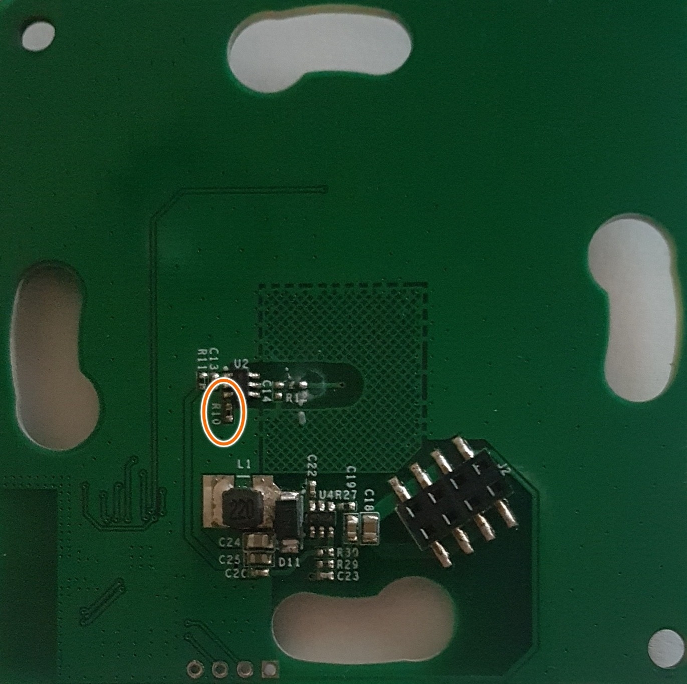
The GPIO pin 0 needs to be connected to ground for the Sonoff T4 to be put into flashing mode. This is best achieved by connecting R10 (on the back of the PCB) to GND for ~10 seconds while the device is turned on (you connect the 3v3 from your serial adaptor).
GUI flashing tools (for beginners)
Among your options are Tasmotizer and ESPHome-flasher. Both are extremely intuitive so I won’t bother explaining how to use them.
Flashing with esptool.py (slightly more advanced)
ESPTool requires either Python2.7, Python3.4 or newer. The latest stable release is easily installed with:
$ pip2 install esptool # For Python2
$ pip3 install esptool # For Python3
- Getting errors with pip3? Try
python -m pip install esptool - On Windows or want an executable? Try this instead of installing with pip.
(Optional) make a backup of the flash
You can do this with esptool.py -p PORT read_flash 0 0x100000 flash_contents.bin, where PORT depends on whether you are on Windows, using a USB adaptor, or Raspberry Pi. A new file will be created in your current working directory, called flash_contents.bin.
The Sonoff T4 works with the default baud rate of 115200. You do not need to bother changing this.
Writing your new binary
Now, you must power-cycle the device. Disconnect the 3v3 from your RPI / serial adaptor, short R10 to ground (using a jumper wire again), reconnect 3v3, wait 10 seconds, stop shorting R10 to ground.
After power cycling the device, you can upload the new firmware with the following command:
$ esptool.py -p PORT write_flash 0x0 your_new_firmware.bin
Disconnect 3v3 one final time, then reconnect it (without the jumper wire between R10 and GND). Your T4 should connect to whatever WiFi network you specified when compiling the binary, and it should be fully functional (minus not having the relay connected). Once you have verified the device works, you can disconnect your serial adaptor / RPI and install the T4 in the desired location (following the instructions from the original manual).
Making and uploading (OverTheAir) the final firmware
Below you can find all three controllable components and which GPIO pin they are connected to. This will be helpful for you to configure your custom firmware.
| GPIO # | Component | Notes |
|---|---|---|
| GPIO0 | Touch Button 1 | Inverted |
| GPIO12 | Relay 1 | Inverted |
| GPIO13 | Led 1 | Inverted |
There currently only exists one variant of the T4, called T4EU1C. It only has one touch button and relay. If a 2 channel variant is released, the second relay will likely be on GPIO pin 5 and the second button on pin 9.
My own configuration for ESPHome
esphome:
  name: light_switch
  platform: ESP8266
  board: esp01_1m

wifi:
  ssid: "Thomas Home"
  password: "NOPE!!"

  # Enable fallback hotspot (captive portal) in case wifi connection fails
  ap:
    ssid: "Light Switch"
    password: "NOPE!!"

captive_portal:

# Enable logging
logger:

# Enable Home Assistant API
api:

ota:

binary_sensor:
  - platform: gpio
    pin:
      number: GPIO0
      mode: INPUT_PULLUP
      inverted: true
    id: button_1
    on_press:
      then:
        - light.toggle: light_1

output:
  - platform: gpio
    pin: GPIO12
    id: relay_1

light:
  - platform: binary
    name: "Light"
    id: light_1
    output: relay_1

status_led:
  pin:
    number: GPIO13
    inverted: true
Comments